- 您现在的位置:买卖IC网 > Sheet目录1012 > V23026A1002B201 (TE Connectivity)RELAY GEN PURPOSE SPDT 1A 12V
�� �
�
�Signal� Relays�
�P1� Relay� V23026� (Continued)�
�AXICOM�
�Coil� data� (continued)�
�Coil� versions,� THT� and� SMT,� bistable� 2� coils�
�Coil� Rated� Set� Reset� Coil� Rated� coil�
�code� voltage� voltage� voltage� resistance� power�
�VDC� VDC� VDC� ?� ±10%� mW�
�106� 3� 2.25� 2.25� 130� 69�
�101� 5� 3.75� 3.75� 390� 64�
�105� 9� 6.75� 6.75� 1200� 68�
�102� 12� 9.00� 9.00� 1500� 96�
�24� 1)�
�All� figures� are� given� for� coil� without� pre-energization,� at� ambient� temperature� +23°C.�
�Coils� I� and� II� are� identical.�
�1)� A� nominal� voltage� of� 24VDC� is� feasible� with� a� 12VDC� coil� with� a� series� resistor� (1500?)�
�Insulation� Data�
�Initial� dielectric� strength�
�between� open� contacts�
�between� contact� and� coil�
�Initial� surge� withstand� voltage�
�between� contact� and� coil�
�Capacitance�
�between� open� contacts�
�between� contact� and� coil�
�Clearance/creepage�
�between� contact� and� coil�
�between� adjacent� contacts�
�500V� rms�
�1500V� rms�
�2500V�
�max.� 5pF�
�max.� 6pF�
�0.75mm�
�0.75mm�
�AXICOM�
�Coil� versions,� THT,� bistable� 1� coil� T� elecom-,� Signal� and� RF� Relays�
�P1� V23026� resistance�
�Relay� power�
�nom.� nominal� coil� voltage�
�Other� coil� voltages� U� on� request�
�at� 100MHz/900MHz� 1.06/1.75�
�U� nom� Category� of� Nominal� coil� voltage�
�=�
�=� Lower� limit� of� the� operative� range� of�
�U� rel.� min.�
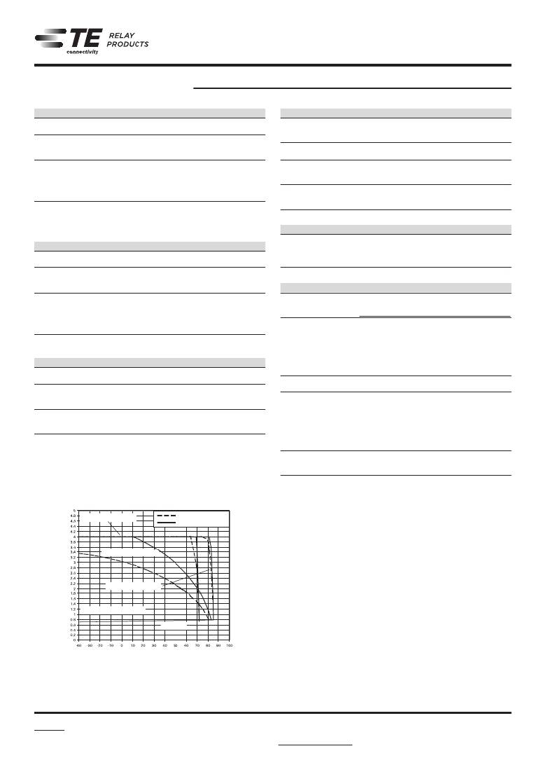
�Coil� operative� range,� bistable� Temperature� [°C]�
�Coil data� (continued)�
�Coil� Rated� Set� Reset� Coil� Rated� coil�
�code� voltage� voltage� voltage�
�VDC� VDC� VDC� ?� ±10%� mW�
�056� 3� 2.25� -2.25� 300� 30�
�051� 5� 3.75� -3.75� 740� 34�
�057 9 6.75�
�Coil� Operating� Range� -6.75� 2160� 38�
�052� 12� 9.00� -9.00� 4500� 32�
�054� 24� 18.00� -18.00� 4500� 128�
�65� mW�
�130� mW�
�Coil� data� (continued)�
�U� max.� at� 0� A�
�0A� max.�
�Coil� versions,� U� SMT,� at� bistable� 1� coil� U� max.� at� -� 1� A�
�Coil� Rated� Set� Reset� Coil� Rated� coil�
�code� voltage� voltage� voltage� resistance� power�
�VDC� VDC� VDC� ?� ±10%� mW�
�051� 5� 3.75� -3.75� 740� 34�
�052� 12� 9.00� -9.00� 4500� 32�
�A� nominal� voltage� of� 24V� is� feasible� with� a� 12V� coil� with� a� series� resitor� (4500?)�
�All� figures� are� given� for� coil� without� pre-energization,� at� ambient� temperature� +23°C.�
�Coils� I� and� II� are� identical.� U� op.� min.�
�U� rel.� min.�
�Ambient�
�RF� Data�
�Isolation� at� 100MHz/900MHz� -30.0dB/-18.0dB�
�Insertion� loss� at� 100MHz/900MHz� -0.12dB/-1.9dB�
�Voltage� standing� wave� ratio� (VSWR)�
�108-98009� Rev.� E�
�Other� Data�
�Material� compliance:� EU� RoHS/ELV,� China� RoHS,� REACH,� Halogen� content�
�refer� to� the� Product� Compliance� Support� Center� at�
�www.te.com/customersupport/rohssupportcenter�
�Ambient� temperature� -40� to� +85°C�
�environmental� protection,�
�IEC� 61810� RT� III� -� immersion� cleanable�
�= Upper the of�
�U� max.� Vibration� resistance� limit� (functional)� operative� range� 20g,� 200� to� 2000Hz�
�whencoilsare�
�the� coil� voltage� (limiting� voltage)� 40g,� 10� to� 200Hz�
�Shock� resistance� (functional)� continously� energized�
�IEC� 60068-2-27� (half� sine)� 50� g�
�min.� =type rangeof�
�U� op.� Terminal� Lower� limit� of� the� operative� PCB� terminals� and� SMT� terminals�
�Weight� the� coil� voltage� (reliable� operate� max.� 2g�
�voltage)�
�Resistance� soldering� heat� THT�
�IEC� 60068-2-20� 265� °C/10s�
�Resistance� to� soldering� heat� SMT�
�thecoil�
�sensitive�
�IEC� 60068-2-58� voltage� (reliable� release� see� reflow� profile�
�Moisture� voltage)� level,� JEDEC� J-Std-020D� MSL3�
�Washing� not� recommended�
�Ultrasonic� cleaning� possible�
�Packaging� unit�
�THT� 2000� pcs.�
�SMT� 2400� pcs.�
�U� max�
�upper� limit� of� the� operative� range� of� the� coil� voltage� (limiting� voltage)� when� coils� are�
�U� max.� -� 5� %� coil� duty� at� 1� A�
�U� max.� -� 100� %� coil� duty� at� 0� A�
�65� mW� Latching�
�32� mW� Latching�
�U� max.� -� 5� %� coil� duty� at�
�0A�
�U� nom.� nominal coil voltage�
�U� set� min.�
�Ambient� Temperature� [°C]�
�continuously� energized.�
�U� op� min� lower� limit� of� the� operative� range� of� the� coil� voltage� (reliable� operate� voltage).�
�U� rel� min� lower� limit� of� the� operative� range� of� the� coil� voltage� (reliable� release� voltage).�
�2�
�02-2012,� Rev.� 0212�
�www.te.com�
�?� 2011� Tyco� Electronics� Corporation,�
�a� TE� Connectivity� Ltd.� company�
�Datasheets� and� product� specification�
�according� to� IEC� 61810-1� and� to� be� used�
�only� together� with� the� ‘Definitions’� section.�
�Datasheets� and� product� data� is� subject� to� the�
�terms� of� the� disclaimer� and� all� chapters� of�
�the� ‘Definitions’� section,� available� at�
�http://relays.te.com/definitions�
�Datasheets,� product� data,� ‘Definitions’� sec-�
�tion,� application� notes� and� all� specifications�
�are� subject� to� change.�
�发布紧急采购,3分钟左右您将得到回复。
相关PDF资料
V23047-A1110-A501
RELAY SAFETY DPDT 6A 110V
V23050A1048A542
RELAY SAFETY 6PST 8A 48V
V23054D1003F104
RELAY GEN PURPOSE DPDT 5A 220V
V23079A2003B301
RELAY GEN PURPOSE DPDT 2A 12V
V23079B1202B301
RELAY GENERAL PURPOSE DPDT 2A 6V
V23079D1001B301
RELAY GENERAL PURPOSE DPDT 2A 5V
V23079E1206B301
RELAY GENERAL PURPOSE DPDT 2A 9V
V23079F1108B301
RELAY GENERAL PURPOSE DPDT 2A 3V
相关代理商/技术参数
V23026-A1002-B201
制造商:TE Connectivity 功能描述:RELAY PCB SPCO 12VDC 制造商:TE Connectivity 功能描述:RELAY, PCB, SPCO, 12VDC
V23026-A1002-B201
制造商:TE Connectivity 功能描述:RELAY PCB SPCO 12VDC
V23026A1003B201
功能描述:低信号继电器 - PCB RoHS:否 制造商:NEC 触点形式:2 Form C (DPDT-BM) 触点电流额定值: 线圈电压:5 V 最大开关电流:1 A 线圈电流:1 A 线圈类型:Non-Latching 功耗:140 mW 端接类型:SMT 绝缘: 介入损耗:
V23026-A1003-B201
制造商:Tyco Electronics 功能描述:Bulk
V23026A1004B201
功能描述:低信号继电器 - PCB 24VDC Non-latching Single coil P1
RoHS:否 制造商:NEC 触点形式:2 Form C (DPDT-BM) 触点电流额定值: 线圈电压:5 V 最大开关电流:1 A 线圈电流:1 A 线圈类型:Non-Latching 功耗:140 mW 端接类型:SMT 绝缘: 介入损耗:
V23026-A1004-B201
制造商:TE Connectivity 功能描述:RELAY PCB SPCO 24VDC 制造商:TE Connectivity 功能描述:RELAY, PCB, SPCO, 24VDC
V23026-A1004-B201
制造商:TE Connectivity 功能描述:RELAY PCB SPCO 24VDC
V23026A1005B201
功能描述:通用继电器 Relays Signal, Up to 2 Amps @ 30 VDC - RELAY PC MNT SPDT 1A 9VDC RoHS:否 制造商:Omron Electronics 触点形式:1 Form A (SPST-NO) 触点电流额定值:150 A 线圈电压:24 VDC 线圈电阻:144 Ohms 线圈电流:167 mA 切换电压:400 V 安装风格:Chassis 触点材料: